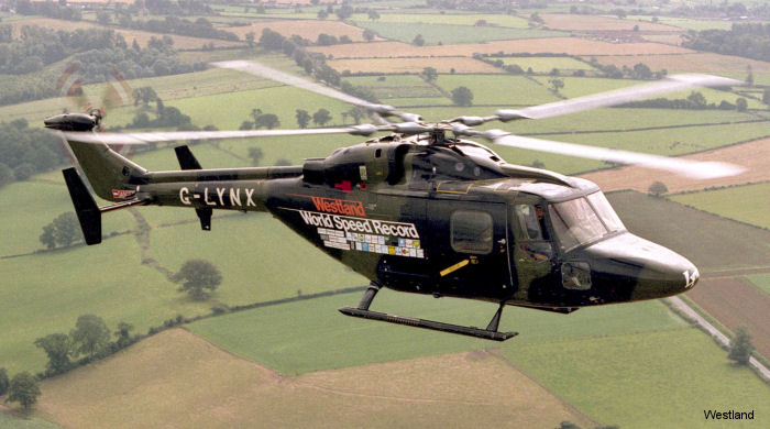
The Westland Lynx reached 402 kph (250 mph) in 1986 using specially designed high-speed rotor blades
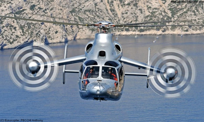
The Eurocopter X3, an experimental compound helicopter, reached 430 kph (267 mph) in 2011
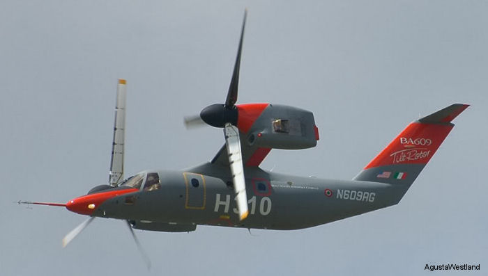
The AgustaWestland AW609 is a tilt-rotor, and can fly at 500 kph (310 mph)
In the following paragraphs, the reasons for this will be discussed in detail.
For ease of explanation, all descriptions will be based on a simple two bladed
rotor system , which rotates counter-clockwise when viewed from above.
This makes the advancing blade on the right side of the aircraft swinging toward
the front of the helicopter.
The explanations will deliberately be kept fairly basic. For the more advanced out there, please don't send e-mail saying that there is more to it than has been stated. However, do comment if you consider that any of the explanations are fundamentally wrong.
There are a number of factors that govern the maximum speed of a helicopter :
 Drag
In aerodynamics, drag is the force opposing thrust. Drag is present in helicopters
in two main types:
Drag
In aerodynamics, drag is the force opposing thrust. Drag is present in helicopters
in two main types:
a. Parasite drag Parasite drag is the drag forces created by the components that protrude into the airflow around the helicopter. Because this drag is opposing thrust it is reducing the amount of thrust available to make the helicopter fly faster. Parasite drag includes the landing gear, antennas, cowlings, doors, etc. The shape of the fuselage will also produce parasite drag. On later helicopters where the manufacturer has attempted to raise the speed of the helicopter, the landing gear is retractable to reduce the amount of parasite drag produced. Generally, for a given structure, the amount of parasite drag is proportional to the speed that the structure is passing through the air and therefore parasite drag is a limiting factor to airspeed.
b. Profile drag Profile drag is the drag produced by the action of the rotor blades being forced into the oncoming airflow. If a rotor blade was cut in half from the front of the blade (leading edge) to the rear of the blade (trailing edge), the resulting shape when looking at the cross-section is considered to be the blade "profile". For a rotor blade to produce lift, it must have an amount of thickness from the upper skin to the lower skin, which is called the "camber" of the blade. In general terms the greater the camber, the greater the profile drag. This is because the oncoming airflow has to separate further to pass over the surfaces of the rotor blade. The blade profile for a given helicopter has been designed as a compromise between producing sufficient lift for the helicopter to fulfill all of its roles, and minimising profile drag. To alter the amount of lift produced by the rotor system, the angle of attack must be altered. As the angle of attack is increased then the profile drag also increases. This is generally referred to as "induced drag", as the drag is induced by increasing the angle of attack.
Have you ever stuck your hand out of the window while travelling in a car? If so, did you notice that if you kept your hand flat with your thumb leading then you could keep you hand in that position fairly easily with some effort. What happens if you turn your hand so that your palm is facing into the wind? It is not as easy now to keep you hand still and it requires far greater effort to keep it there. This can be related to profile drag and induced drag.
Retreating Blade Stall
To understand retreating blade stall it is first necessary to understand a condition known as
"Dissymetry of Lift".
Consider a helicopter hovering in still air and at zero ground speed. The pilot is maintaining a constant blade pitch angle with the collective pitch control lever and the aircraft is at a constant height from the ground. The airflow velocity over the advancing blade and the retreating blade is equal.
If the tip of the advancing blade is travelling at 300mph then the tip of the retreating blade must also be travelling at 300mph. The velocity of the airflow over the blade is progressively reduced as we look closer toward the root end of the blade (toward the rotor hub) as the distance that the observed point has to travel around the circle is reduced.
In this condition the amount of lift being generated by each blade is the same because the amount of lift produced is a function of velocity and angle of attack. However, if the helicopter started to move forward then the airflow velocity over the advancing blade would be increased by the amount of the forward speed as the blade is moving in the opposite direction to the flight. If the helicopter was then travelling forward at 100mph, then the airflow at the advancing blade tip would be:
At the retreating blade the velocity is reduced by the amount of forward speed as the blade is travelling in the same direction as the airflow created by forward flight. So the tip is now effectively travelling at 200mph, or half the speed of the advancing blade. From the Formula for Lift, it is known that the amount of lift produced varies as the square of velocity. From the example above this means that the advancing blade will produce four times more lift than the retreating blade. If this situation was not corrected, the helicopter could not fly forward in a straight line when forward flight was attempted. (It would actually pitch nose-up, but that's another story!)
To correct for this the rotor system is allowed to "flap" whereby one blade tip can rise above the other with reference to the rotor plane of rotation. The effect this has is to reduce lift on the advancing blade and increase lift on the retreating blade. The lift across both blades is then equalised.
Now that we understand "Dissymetry of Lift", we can look at retreating blade stall. You will recall that the retreating blade has a lower airflow velocity than the advancing blade in forward flight. If we were to accelerate our helicopter from the above example to 300mph, then the advancing blade would have an airflow velocity of 600mph, and the retreating blade would be zero. For the blade to produce lift it must have some airflow over it, so in this case the blade would "stall". Stall is a condition where there is a breakdown of smooth laminar airflow over the surfaces of an aerofoil (rotor blade).
With each blade entering a stall condition as it passed down the left side of the helicopter, forward flight could not be maintained at this speed. Before the blade actually stalled it would produce a series of harsh vibrations known as "buffeting". When a manufacturer produces a new helicopter, the speed at which this buffeting will occur is established during flight test trials and a lower figure is subsequently published which is commonly known as VNE or Velocity - Never Exceed . This establishes a safety margin below the speed where retreating blade stall may occur.
Airflow Reversal
Airflow Reversal will normally occur before retreating blade stall. You will recall that the airflow velocity is progressively reduced along a blade from being highest at the tip, to lowest at the root end.
If the velocity is 300mph at the tip, it is feasible for the velocity to be as low as 100mph at the root. Therefore when forward speeds as low as 100mph (approx. 87 Kts) are encountered, the root end of the blade is effectively stalled. When higher speeds are attempted, the airflow across the root end of the blade can actually reverse and travel from the trailing edge to the leading edge. This is because the airflow velocity produced by the forward speed is greater than that being produced by the rotor blades turning. Airflow reversal is counter-productive to producing lift and rotor thrust.
To reduce the effects of lift variations from the root to the tip of a blade the manufacturer will either twist the blade along its length, or apply a taper to the blade. Twist is the reduction of angle of attack from the root to the tip. Remember that lift increases with velocity and angle of attack? Because the tip is travelling faster than the root, the angle of attack must be reduced toward the tip to maintain the same amount of lift at the tip and the root ends. Taper is the gradual reduction of the width of a blade from the leading edge to the trailing edge. A straight line drawn from the centre of the leading edge to the centre of the trailing edge is called the "Chord Line". By reducing the chord line from the root to the tip, less surface area is available for the airflow to act on to produce lift.
On higher speed helicopters (Westland Lynx), the root end of the blade is a blade spar and attachment area only. The aerofoil shape does not start until several feet out from the centre of the rotor system. This is done to reduce the effects of airflow reversal by placing the lift-producing surface further out where the rotational velocity is higher.
Air Compressibility
Air is a gas and therefore conforms to the properties of a gas, namely the ability to be compressed. When studying aerodynamics however, air must also be considered to have some of the properties of a fluid. A fluid has far less compressibility than a gas.
When the airflow over a rotor blade strikes the leading edge, it is split into two streams, which then pass above and below the blade. At lower speeds, this splitting action occurs relatively easily requiring little energy. As speeds increase, the air striking the leading edge tends to be compressed before separating into two streams. Think of this as slapping your hand onto a water surface. If you chop your hand into the water, like a karate chop, you can separate the water fairly easily. If you slap your open hand onto the water however, it takes considerably more force to submerge your hand. The airflow at the leading edge is very similar. As the air at the leading edge is progressively compressed, it requires considerably more rotor thrust for the blade to separate the airflow into two streams.
Cyclic Control Stick design
Helicopter designers are forever trying to fit more equipment into the cockpit of a helicopter to satisfy market demands. At the same time, they are trying to minimise the weight of the aircraft so that it can carry and lift more. When designing the pilot and copilots workstations the designers attempt to place the controls in a position where the crew can easily and comfortably operate all controls without excessive reaching or stretching. This places limitations on the amount of movement available at the cyclic control stick.
The designers could feasibly arrange the controls such that very small amounts of stick movement were required for normal flight, but this would make control in the hover very difficult as the controls would be super sensitive to small inputs. For this reason, the controls are arranged so that a reasonable control movement is available, generally 6-8 inches of stick movement depending on the particular aircraft model.
Available Engine Power
The engine system in a helicopter is required to provide power for a range of demands, not only the rotor system. In the rotor system, thrust is required to overcome drag. As speed is increased, so does drag. If more power is available to overcome drag, then potentially the helicopter can fly faster.
Summary It can be seen that from these factors that it is very difficult for helicopter designers to increase the maximum speed of a helicopter as many factors are beyond their control. Much research and development has occurred in areas such as reducing drag, better rotor blade designs and increasing available engine power.
The explanations will deliberately be kept fairly basic. For the more advanced out there, please don't send e-mail saying that there is more to it than has been stated. However, do comment if you consider that any of the explanations are fundamentally wrong.
There are a number of factors that govern the maximum speed of a helicopter :
a. Parasite drag Parasite drag is the drag forces created by the components that protrude into the airflow around the helicopter. Because this drag is opposing thrust it is reducing the amount of thrust available to make the helicopter fly faster. Parasite drag includes the landing gear, antennas, cowlings, doors, etc. The shape of the fuselage will also produce parasite drag. On later helicopters where the manufacturer has attempted to raise the speed of the helicopter, the landing gear is retractable to reduce the amount of parasite drag produced. Generally, for a given structure, the amount of parasite drag is proportional to the speed that the structure is passing through the air and therefore parasite drag is a limiting factor to airspeed.
b. Profile drag Profile drag is the drag produced by the action of the rotor blades being forced into the oncoming airflow. If a rotor blade was cut in half from the front of the blade (leading edge) to the rear of the blade (trailing edge), the resulting shape when looking at the cross-section is considered to be the blade "profile". For a rotor blade to produce lift, it must have an amount of thickness from the upper skin to the lower skin, which is called the "camber" of the blade. In general terms the greater the camber, the greater the profile drag. This is because the oncoming airflow has to separate further to pass over the surfaces of the rotor blade. The blade profile for a given helicopter has been designed as a compromise between producing sufficient lift for the helicopter to fulfill all of its roles, and minimising profile drag. To alter the amount of lift produced by the rotor system, the angle of attack must be altered. As the angle of attack is increased then the profile drag also increases. This is generally referred to as "induced drag", as the drag is induced by increasing the angle of attack.
Have you ever stuck your hand out of the window while travelling in a car? If so, did you notice that if you kept your hand flat with your thumb leading then you could keep you hand in that position fairly easily with some effort. What happens if you turn your hand so that your palm is facing into the wind? It is not as easy now to keep you hand still and it requires far greater effort to keep it there. This can be related to profile drag and induced drag.
If the tip of the advancing blade is travelling at 300mph then the tip of the retreating blade must also be travelling at 300mph. The velocity of the airflow over the blade is progressively reduced as we look closer toward the root end of the blade (toward the rotor hub) as the distance that the observed point has to travel around the circle is reduced.
In this condition the amount of lift being generated by each blade is the same because the amount of lift produced is a function of velocity and angle of attack. However, if the helicopter started to move forward then the airflow velocity over the advancing blade would be increased by the amount of the forward speed as the blade is moving in the opposite direction to the flight. If the helicopter was then travelling forward at 100mph, then the airflow at the advancing blade tip would be:
| Velocity induced by the blades turning: | 300mph |
| Plus the velocity from forward flight: | 100mph |
| Total effective velocity at the tip: | 400mph |
At the retreating blade the velocity is reduced by the amount of forward speed as the blade is travelling in the same direction as the airflow created by forward flight. So the tip is now effectively travelling at 200mph, or half the speed of the advancing blade. From the Formula for Lift, it is known that the amount of lift produced varies as the square of velocity. From the example above this means that the advancing blade will produce four times more lift than the retreating blade. If this situation was not corrected, the helicopter could not fly forward in a straight line when forward flight was attempted. (It would actually pitch nose-up, but that's another story!)
To correct for this the rotor system is allowed to "flap" whereby one blade tip can rise above the other with reference to the rotor plane of rotation. The effect this has is to reduce lift on the advancing blade and increase lift on the retreating blade. The lift across both blades is then equalised.
Now that we understand "Dissymetry of Lift", we can look at retreating blade stall. You will recall that the retreating blade has a lower airflow velocity than the advancing blade in forward flight. If we were to accelerate our helicopter from the above example to 300mph, then the advancing blade would have an airflow velocity of 600mph, and the retreating blade would be zero. For the blade to produce lift it must have some airflow over it, so in this case the blade would "stall". Stall is a condition where there is a breakdown of smooth laminar airflow over the surfaces of an aerofoil (rotor blade).
With each blade entering a stall condition as it passed down the left side of the helicopter, forward flight could not be maintained at this speed. Before the blade actually stalled it would produce a series of harsh vibrations known as "buffeting". When a manufacturer produces a new helicopter, the speed at which this buffeting will occur is established during flight test trials and a lower figure is subsequently published which is commonly known as VNE or Velocity - Never Exceed . This establishes a safety margin below the speed where retreating blade stall may occur.
If the velocity is 300mph at the tip, it is feasible for the velocity to be as low as 100mph at the root. Therefore when forward speeds as low as 100mph (approx. 87 Kts) are encountered, the root end of the blade is effectively stalled. When higher speeds are attempted, the airflow across the root end of the blade can actually reverse and travel from the trailing edge to the leading edge. This is because the airflow velocity produced by the forward speed is greater than that being produced by the rotor blades turning. Airflow reversal is counter-productive to producing lift and rotor thrust.
To reduce the effects of lift variations from the root to the tip of a blade the manufacturer will either twist the blade along its length, or apply a taper to the blade. Twist is the reduction of angle of attack from the root to the tip. Remember that lift increases with velocity and angle of attack? Because the tip is travelling faster than the root, the angle of attack must be reduced toward the tip to maintain the same amount of lift at the tip and the root ends. Taper is the gradual reduction of the width of a blade from the leading edge to the trailing edge. A straight line drawn from the centre of the leading edge to the centre of the trailing edge is called the "Chord Line". By reducing the chord line from the root to the tip, less surface area is available for the airflow to act on to produce lift.
On higher speed helicopters (Westland Lynx), the root end of the blade is a blade spar and attachment area only. The aerofoil shape does not start until several feet out from the centre of the rotor system. This is done to reduce the effects of airflow reversal by placing the lift-producing surface further out where the rotational velocity is higher.
When the airflow over a rotor blade strikes the leading edge, it is split into two streams, which then pass above and below the blade. At lower speeds, this splitting action occurs relatively easily requiring little energy. As speeds increase, the air striking the leading edge tends to be compressed before separating into two streams. Think of this as slapping your hand onto a water surface. If you chop your hand into the water, like a karate chop, you can separate the water fairly easily. If you slap your open hand onto the water however, it takes considerably more force to submerge your hand. The airflow at the leading edge is very similar. As the air at the leading edge is progressively compressed, it requires considerably more rotor thrust for the blade to separate the airflow into two streams.
The designers could feasibly arrange the controls such that very small amounts of stick movement were required for normal flight, but this would make control in the hover very difficult as the controls would be super sensitive to small inputs. For this reason, the controls are arranged so that a reasonable control movement is available, generally 6-8 inches of stick movement depending on the particular aircraft model.
Summary It can be seen that from these factors that it is very difficult for helicopter designers to increase the maximum speed of a helicopter as many factors are beyond their control. Much research and development has occurred in areas such as reducing drag, better rotor blade designs and increasing available engine power.